Home / Broadband Downhole Acoustic Recording During Perforation
Broadband Downhole Acoustic Recording During Perforation
Broadband Downhole Acoustic Recording During Perforation
A Broadband Perforation Recorder for Event Identification and Acoustic Analysis
Perforating a formation in a cased well is one of the most critical operations in well completion. Its success directly affects formation testing, fluid inflow, and the subsequent production performance of the well.
Shaped-charge perforating guns are commonly deployed on tubing, including in highly deviated, inclined, and horizontal wells where wireline deployment may not be possible.
During tubing-conveyed perforating operations, it is essential to confirm that the perforating gun has actually fired. If a gun fails to fire, retrieving it from the well requires additional safety procedures.
In many cases, gun firing is identified from indirect surface indications such as vibration, acoustic noise, or changes in the fluid volume at the wellhead. However, these indications may be weak or difficult to distinguish from background noise generated by pumps, engines, and other equipment operating at the wellsite.
Another important limitation is the absence of a permanent record that can be reviewed later to confirm what actually happened during the perforation operation.
From shot detection to acoustic recording
To address these challenges, we developed a Broadband Perforation Recorder.
The purpose of the instrument is not simply to indicate that a perforator has fired. It is designed to record the acoustic signature of the perforation event in the steel casing, store the data digitally, and provide a basis for subsequent analysis.
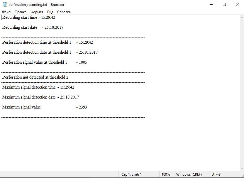
The acoustic signal is recorded in the instrument’s internal memory in WAVE format. A separate text file is generated to accompany the recording and contains the date, time, and amplitude information associated with the registered signal (Fig. 1).
The Recorder also includes a threshold-based firing indicator for immediate operational monitoring.
An important feature is that crossing the firing-indicator threshold does not automatically terminate the recording. Recording continues until the operator switches the instrument off or the available memory is filled.
This approach helps prevent the loss of potentially important information caused by a false trigger or an unexpected disturbance.
In other words, the threshold indicator can provide an immediate operational response, while the broadband recording preserves the complete acoustic event for subsequent analysis.
Recorder design and field operation
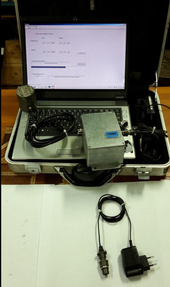
The Broadband Perforation Recorder consists of an electronic unit housed in a sealed metal enclosure and a sensor connected by a flexible cable. The sensor is equipped with a magnetic mounting system.
The complete system includes the Recorder, charger, personal computer, and data-transfer cable (Fig. 2).
Before installation, the internal memory of the Recorder should be cleared.
The sensor can be installed at the wellhead using its magnetic mounting system. No special mechanical preparation is required; the operator simply selects an appropriate installation location.
After the operation, the recorded data can be transferred to a personal computer for viewing, listening, and further analysis using the associated software.
Fig. 1. Broadband recording of a perforation event.
Main technical specifications
Maximum recording time: 30 min.
Maximum total operating time with the switch in the ON position after a full battery charge: 200 min.
Batteries: 2 × Enersys Cyclon, 2 V, 2.5 Ah.
First perforation-event indication threshold: 5000 units (blue LED).
Second perforation-event indication threshold: 8000 units (red LED).
Maximum acceleration for the sensor: 100 g.
Overall dimensions (L × W × H): 220 × 150 × 100 mm.
Weight including sensor: 2.4 kg.
Operating temperature range: −45°C to +45°C.
Fig. 2. Broadband Perforation Recorder with a remote acoustic sensor.
What does a perforation event look like acoustically?
A perforation shot is not simply a single impulse. The recorded signal may contain a sequence of acoustic events associated with the perforator, the initiating system, the tubing, the casing, and other operations taking place during the job.
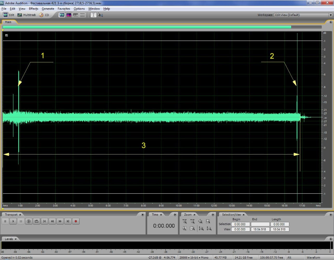
Figure 3 shows an acoustic record of a perforation operation using a hydraulic initiating device (HID). Several sections of the recording correspond to individual events.
The perforator firing signal has characteristic features that distinguish it from other acoustic sources present during the operation.
In the recorded example, the signal level generated by perforator firing exceeds −1 dB, while the noise generated by the operating pumping units does not exceed −21 dB.
This difference in signal level provides a clear basis for identifying the firing event in the recorded data.
A reference signal is artificially generated at the beginning of the recording by lightly tapping the area near the sensor with a small metal object, such as a coin. This provides a convenient timing and identification reference for the subsequent analysis.
Resolving individual events within the acoustic record
The broadband recording can contain more information than the simple confirmation of gun firing.
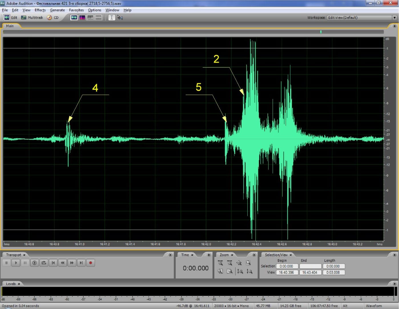
Figure 4 shows an expanded section of the recording presented in Fig. 3. In addition to the perforator firing event (2), the record captures the first contact of the initiating ball with the hydraulic initiating device (4) and the subsequent activation of the HID itself (5).
The ability to resolve these individual events illustrates an important advantage of retaining the complete acoustic record rather than relying only on a threshold-based firing indication.
The recorded waveform can be reviewed after the operation and correlated with the sequence of mechanical and hydraulic events.
Mechanical initiation and reflected acoustic waves
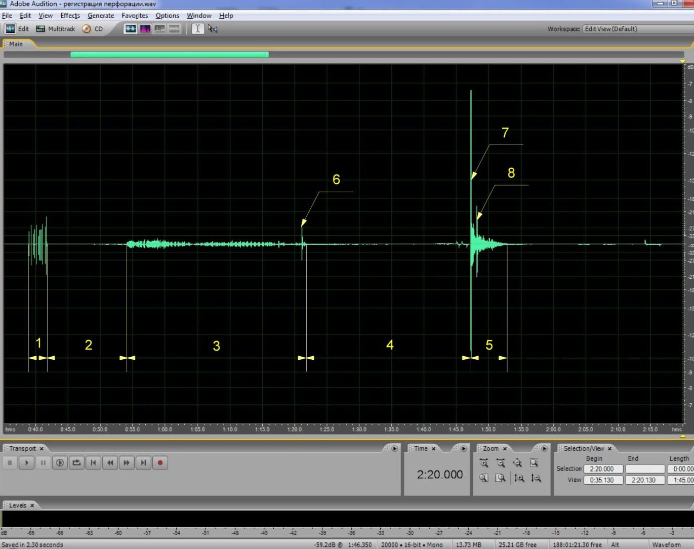
Figure 5 shows an acoustic record obtained during a perforation operation using a mechanical initiating device.
As in the previous example, the perforator firing signal has characteristic features that distinguish it from other sources of acoustic noise.
However, another important feature becomes visible in this recording: the reflected acoustic signal travelling along the casing.
The acoustic event generated by the perforator propagates through the steel casing. Part of the signal travels directly to the sensor, while another part is reflected from the casing end and returns toward the surface.
This creates a characteristic pair of arrivals: a direct wave followed by a reflected wave.
Using direct and reflected waves for acoustic analysis
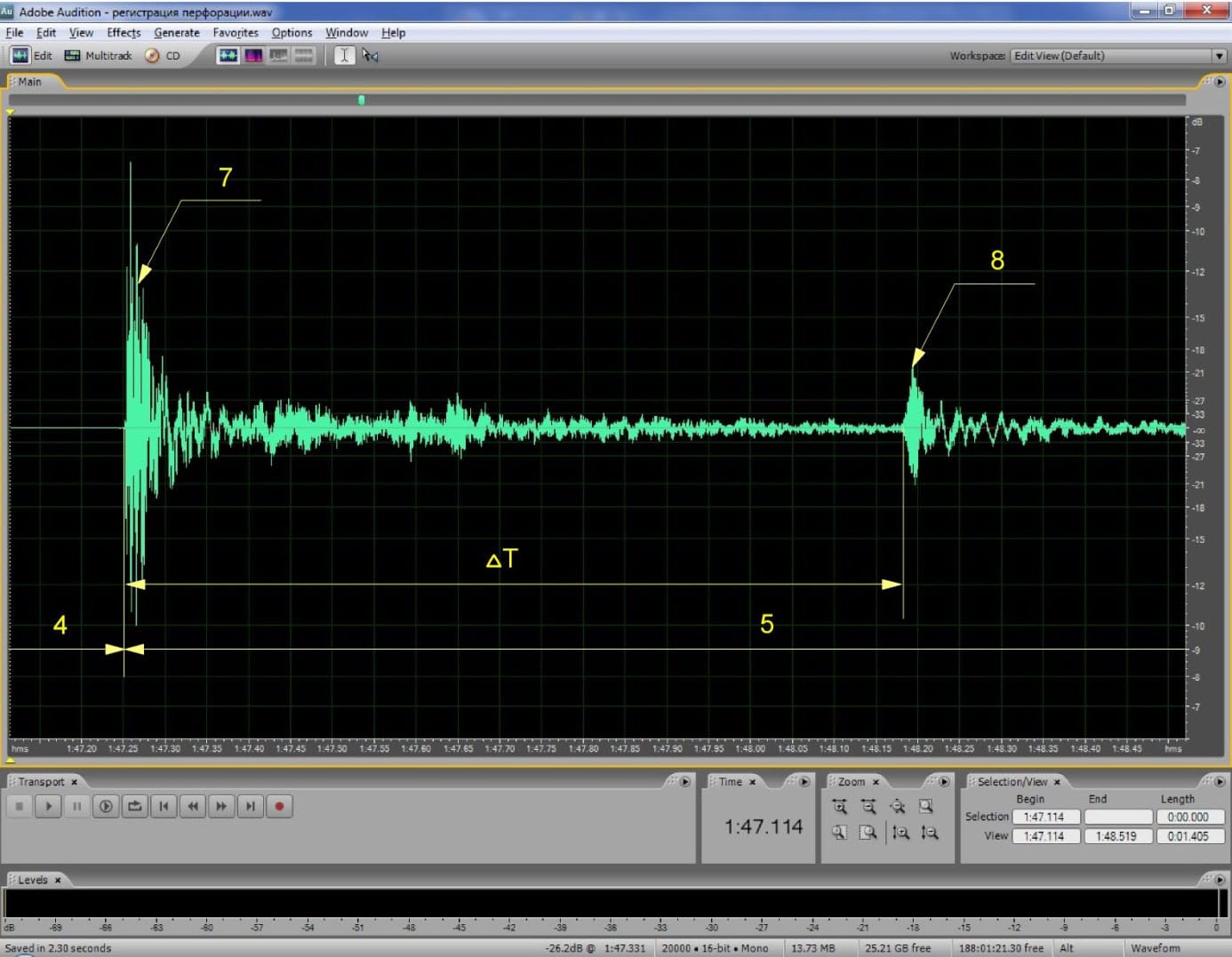
Figure 6 shows an expanded section of the recording containing the direct and reflected waves.
The time interval ΔT between the first arrival of the direct wave (7) and the reflected wave (8) is related to the casing length and the acoustic velocity in the steel casing:
ΔT = 2Lₖ / Vₛ
where:
ΔT — time interval between the arrivals of the direct and reflected waves generated by perforator firing;
Lₖ — casing length;
Vₛ — acoustic wave propagation velocity in the steel casing.
The inverse relationship can therefore be written as:
Vₛ = 2Lₖ / ΔT
The resulting value of Vₛ lies within approximately 5000–5200 m/s. This range accounts for variations in acoustic velocity caused by temperature and casing material.
This example demonstrates that a broadband perforation record can contain information extending beyond simple shot detection. The timing and structure of the recorded acoustic waves can be used to analyze the propagation of the event through the casing.
More than just a firing indicator
The examples presented here do not cover the full variety of acoustic signatures that can occur during well perforation operations.
The recorded acoustic pattern depends on the perforation technology, operating conditions, well construction, and sensor location. The examples should therefore be regarded as illustrations of the capabilities of the Broadband Perforation Recorder rather than as a universal acoustic signature for every perforation job.
Our approach is based on a simple principle:
Record the event first. Analyze it afterwards.
Instead of relying exclusively on a threshold indicator or on subjective surface observations, the complete acoustic record can be preserved for subsequent verification and analysis.
The Recorder can be operated by personnel with basic computer skills and does not require specialized training.
It can also be used in a “black box” mode. In this configuration, the operator installs the sensor at the wellhead, switches the Recorder on before the perforation operation, and switches it off after the operation is completed.
The recorded data can then be transferred and analyzed under laboratory conditions.
Conclusion
A perforation event generates a complex acoustic signature that can contain significantly more information than a simple indication of whether the gun fired.
A broadband recording makes it possible to preserve this information and subsequently examine the timing, amplitude, sequence, and propagation of individual acoustic events.
For tubing-conveyed perforating operations, this provides a practical way to move from simple shot detection to recorded acoustic evidence and event analysis.
Broadband recording turns a momentary perforation event into a permanent dataset available for post-job analysis.
Fig. 3. Acoustic signature of a perforation event with hydraulic initiation. 1 — reference signal; 2 — perforator firing; 3 — noise generated by pumping units.
Fig. 4. Detailed acoustic record of perforator firing and hydraulic initiation. 2 — perforator firing; 4 — contact of the initiating ball with the HID funnel; 5 — activation of the HID.
Fig. 5. Acoustic signature of perforation with mechanical initiation. 1 — reference signal; 2 — operational pause; 3 — opening of the wellhead Christmas tree; 4 — movement of the initiating rod through the tubing; 5 — acoustic wave generated by perforator firing; 6 — release of the initiating rod; 7 — arrival time of the direct wave; 8 — arrival time of the reflected wave.
Fig. 6. Direct and reflected acoustic waves generated by perforator firing. ΔT — time interval between the arrivals of the direct and reflected waves; 4 — movement of the initiating rod through the tubing; 5 — acoustic wave generated by perforator firing; 7 — arrival time of the direct wave; 8 — arrival time of the reflected wave.